LED Pace Clock
This project was originally a personal project, but after some complications I decided to pause the project. I then suggested it as an idea for PickHacks, a hackathon as Missouri S&T where me and some teammates ultimately built it into a working prototype and placed in the top 10.
I wanted to combine my passions; sports and technology. This was a great way to put the two together.
A little background on the project, I swam competitively for several years and I enjoyed having immediate feedback during training. So I came up with this idea of a LED strip pace clock. The strip is placed at the bottom of the pool and you have to race the light. The point of this is to keep pace and it provides immediate and visual feedback. This really helps when you tweak your stroke technique. This LED strip can also be used for track as well since both sports consist of an athlete covering a certain amount of distance over time just in a different medium(water/air).
To build this, the following parts were used:
- Arduino Mega
- 5x WS2812B LED Strip
- 12V 40A Power Supply
- 400 Ohm Resistor
- 12V to 5V Buck Converter (The LED Strip operates at 5V)
The LED strip is connected to an Arduino Mega. The Arduino has code on it that allows it to interface with a GUI that I made using Visual Studio. Below is a wiring diagram of how the LED strip is connected to the Arduino.
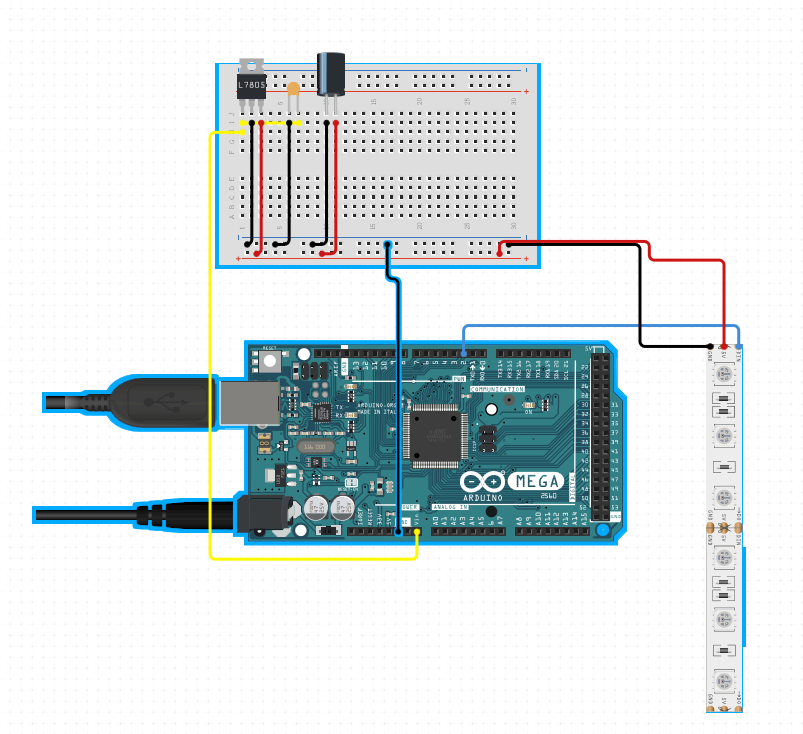 This diagram is not completely accurate as the software I used to design this diagram wouldn’t allow me to place external power supplies. Instead of power and ground wires connecting directly to the Arduino. They are connected to a 5V power supply. The serial connection from the Arduino to the data in pin on the strip is the same.
The most difficult part was parsing the serial data and converting it into data the Arduino could use. The function below takes in the data from the serial port and stores it at as string. That string is then parsed and converted to integer values that the Arduino uses to calculate the speed of the strip, # of repititions, color, etc.
void serialEvent() {
  while (Serial.available()) {
    // get the new byte:
    char inChar = (char)Serial.read();
    // add it to the inputString:
    inputString += inChar;
    // if the incoming character is a newline, set a flag
    // so the main loop can do something about it:
    if (inChar == '\n') {
      stringComplete = true;
    }
  }
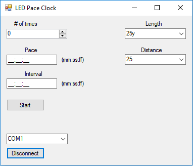
Below is the GUI that I made using Windows Forms. This is written in C#.
Challenges
Originally, multiple serial messages were sent to the Arduino in order to configure all the settings, but the Ardunio’s clock speed was not fast enough to catch the serial messages even when soft interrupts were added. So, a design decision was made to send a single serial message and use bit unpacking.
Another problem with the Arduino’s clock speed was it could not update the LED strip fast enough, so we refreshed 2 pixels at a time instead of 1. The light moves fast enough to where it is not noticeable to the human eye that the light moves 2 at a time.
The strip is 25m in length which is 750 LEDs. Each LED draws 15mA which in total can draw up to 40A. To reduce power consumption, only primary colors are used which reduces current draw to about 7mA. Reducing the brightness can also reduce current draw. With less current draw, the voltage drop isn’t as significant. The voltage drop across the strip was still an issue because of how long the strip is. That is why I opted to use a 12V power supply and then step down to 5V. If we solely operated on 5V we may not have sufficient voltage to power the entire 25m strip
Here is a video of the LED Pace Clock in action.